
The reactors, in which chemicals are made in industry, vary in size from a few cm3 to the vast structures that are often depicted in photographs of industrial plants. For example, kilns that produce lime from limestone may be over 25 metres high and hold, at any one time, well over 400 tonnes of materials.
The design of the reactor is determined by many factors but of particular importance are the thermodynamics and kinetics of the chemical reactions being carried out.
The two main types of reactor are termed batch and continuous.
Batch reactors
Batch reactors are used for most of the reactions carried out in a laboratory. The reactants are placed in a test-tube, flask or beaker. They are mixed together, often heated for the reaction to take place and are then cooled. The products are poured out and, if necessary, purified.
This procedure is also carried out in industry, the key difference being one of size of reactor and the quantities of reactants.
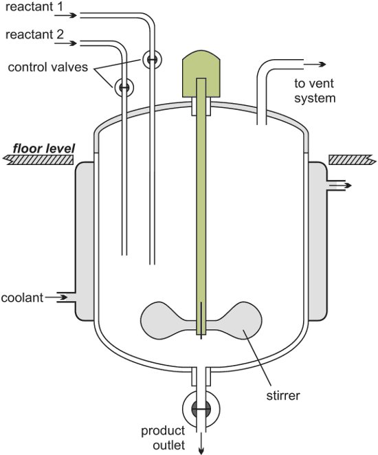
Figure 1 Illustrating a batch reactor.
Following reaction, the reactor is cleaned ready for another batch of reactants to be added.
Batch reactors are usually used when a company wants to produce a range of products involving different reactants and reactor conditions. They can then use the same equipment for these reactions.
Examples of processes that use batch reactors include the manufacture of colorants and margarine.
|
Continuous reactors
An alternative to a batch process is to feed the reactants continuously into the reactor at one point, allow the reaction to take place and withdraw the products at another point. There must be an equal flow rate of reactants and products. While continuous reactors are rarely used in the laboratory, a water-softener can beregarded as an example of a continuous process. Hard water from the mains is passed through a tube containing an ion-exchange resin. Reaction occurs down the tube and soft water pours out at the exit.
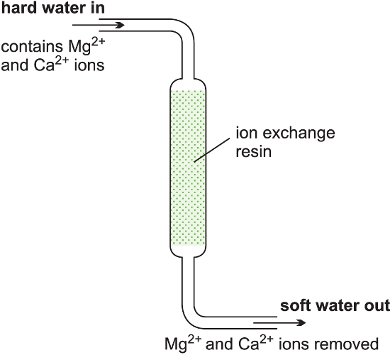
Figure 3 Illustrating a continuous reactor.
Continuous reactors are normally installed when large quantities of a chemical are being produced. It is important that the reactor can operate for several months without a shutdown.
The residence time in the reactor is controlled by the feed rate of reactants to the reactor. For example, if a reactor has a volume of 20 m3 and the feed rate of reactants is 40 m3 h-1 the residence time is 20 m3 /40 m3 h-1 = 0.5 h. It is simple to control accurately the flow rate of reactants. The volume is fixed and therefore the residence time in the reactor is also well controlled.
The product tends to be of a more consistent quality from a continuous reactor because the reaction parameters (e.g. residence time, temperature and pressure) are better controlled than in batch operations.
They also produce less waste and require much lower storage of both raw materials and products resulting in a more efficient operation. Capital costs per tonne of product produced are consequently lower. The main disadvantage is their lack of flexibility as once the reactor has been built it is only in rare cases that it can be used to perform a different chemical reaction.
Types of continuous reactors
Industry uses several types of continuous reactors.
(a) Tubular reactors
In a tubular reactor, fluids (gases and/or liquids) flow through it at high velocities. As the reactants flow, for example along a heated pipe, they are converted to products (Figure 4). At these high velocities, the products are unable to diffuse back and there is little or no back mixing. The conditions are referred to as plug flow. This reduces the occurrence of side reactions and increases the yield of the desired product.
With a constant flow rate, the conditions at any one point remain constant with time and changes in time of the reaction are measured in terms of the position along the length of the tube.
The reaction rate is faster at the pipe inlet because the concentration of reactants is at its highest and the reaction rate reduces as the reactants flow through the pipe due to the decrease in concentration of the reactant.
|
Tubular reactors are used, for example, in the steam cracking of ethane, propane and butane and naphtha to produce alkenes.
(b) Fixed bed reactors
A heterogeneous catalyst is used frequently in industry where gases flow through a solid catalyst (which is often in the form of small pellets to increase the surface area). It is often described as a fixed bed of catalyst (Figure 5).
Among the examples of their use are the manufacture of sulfuric acid (the Contact Process, with vanadium(V) oxide as catalyst), the manufacure of nitric acid and the manufacture of ammonia (the Haber Process, with iron as the catalyst).

Figure 5 Illustrating a fixed bed reactor.
A further example of a fixed bed reactor is in catalytic reforming of naphtha to produce branched chain alkanes, cycloalkanes and aromatic hydrocarbons using usually platinum or a platinum-rhenium alloy on an alumina support.
(c) Fluid bed reactors
A fluid bed reactor is sometimes used whereby the catalyst particles, which are very fine, sit on a distributor plate. When the gaseous reactants pass through the distributor plate, the particles are carried with the gases forming a fluid (Figure 6). This ensures very good mixing of the reactants with the catalyst, with very high contact between the gaseous molecules and the catalyst and a good heat transfer. This results in a rapid reaction and a uniform mixture, reducing the variability of the process conditions.
One example of the use of fluid bed reactors is in the oxychlorination of ethene to chloroethene (vinyl chloride), the feedstock for the polymer poly(chloroethene) (PVC). The catalyst is copper(II) chloride and potassium chloride deposited on the surface of alumina. This support is so fine, it acts as a fluid when gases pass through it.
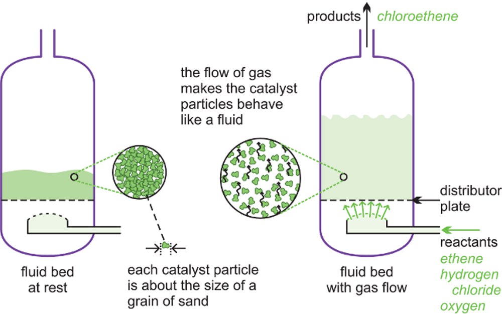 |
| Figure 6 A diagram to illustrate a fluid bed reactor. On the left hand side, the particles are at rest. On the right hand side, the particles are now acting as a fluid, as the gaseous reactants pass through the solid. |
Another example is the catalytic cracking of gas oil to produce alkenes (ethene and propene) and petrol with a high octane rating.

Figure 7 A catalytic cracker as used to produce alkenes from gas oil.
A silica-alumina catalyst is used but fine particles of carbon are rapidly deposited on its surface and the catalyst quickly becomes ineffective. The catalyst, still in the form of a fluid, is regenerated as it passes into a second vessel where it is heated strongly in air (sometimes with added oxygen) burn off the carbon (Figure 7) and then returned into the reaction zone and mixed with gas oil.

Figure 8 Part of the catalytic cracker at Fawley in the south of England.
1 Fractionating column to remove and recover the butanes
2 The catalyst regenerator
3 Fractionating column to remove and recover ethane
By kind permission of ExxonMobil and Pail Carter Photography.
These reactors are larger than fixed bed reactors and are more expensive to construct. However, it is easier to control the conditions and the process is more efficient.
(d) Continuous stirred tank reactors, CSTR
In a CSTR, one or more reactants, for example in solution or as a slurry, are introduced into a reactor equipped with an impeller (stirrer) and the products are removed continuously. The impeller stirs the reagents vigorously to ensure good mixing so that there is a uniform composition throughout. The composition at the outlet is the same as in the bulk in the reactor. These are exactly the opposite conditions to those in a tubular flow reactor where there is virtually no mixing of the reactants and the products.
.jpg)
Figure 9 A line diagram illustrating a continuous stirred tank reactor.
A steady state must be reached where the flow rate into the reactor equals the flow rate out, for otherwise the tank would empty or overflow. The residence time is calculated by dividing the volume of the tank by the average volumetric flow rate. For example, if the flow of reactants is 10 m3 h-1 and the tank volume is 1 m3, the residence time is 1/10 h, i.e. 6 minutes.

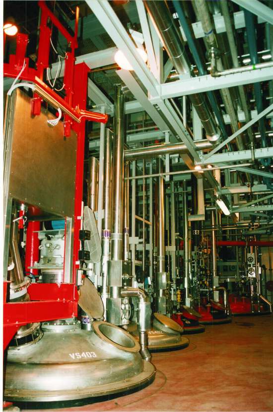
Figure 10 A CSTR reactor, used to make poly(ethene) in bulk.
By kind permission of Total.
A CSTR reactor is used, for example in the production of the amide intermediate formed in the process to produce methyl 2-methylpropenoate. Sulfuric acid and 2-hydroxy-2-methylpropanonitrile are fed into the tank at a temperature of 400 K. The heat generated by the reaction is removed by cooling water fed through coils and the residence time is about 15 minutes.
A variation of the CSTR is the loop reactor which is relatively simple and cheap to construct (Figure 11). In the diagram only one loop is shown. However, the residence time in the reactor is adjusted by altering the length or number of the loops in the reactor.
|
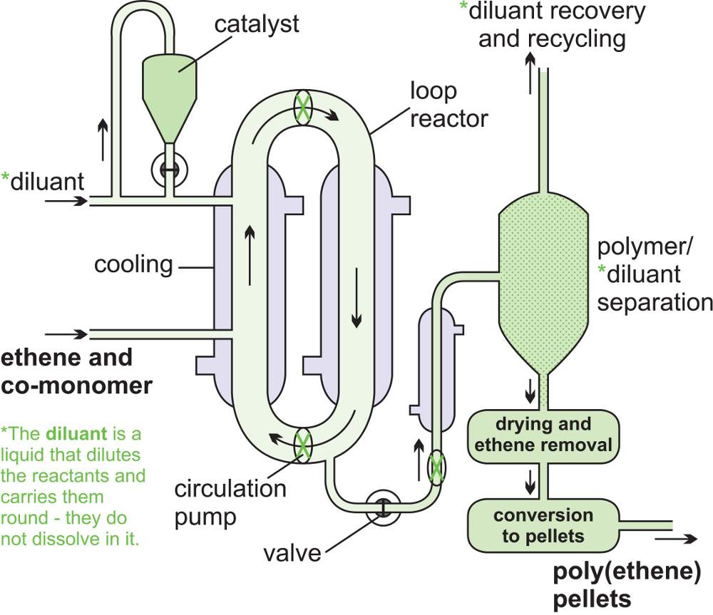
Loop reactors are used, for example, in the manufacture of poly(ethene) and the manufacture of poly(propene). Ethene (or propene) and the catalyst are mixed, under pressure, with a diluent, usually a hydrocarbon. A slurry is produced which is heated and circulated around the loops. Particles of the polymer gather at the bottom of one of the loop legs and, with some hydrocarbon diluent, are continuously released from the system. The diluent evaporates, leaving the solid polymer, and is then cooled to reform a liquid and passed back into the loop system, thus recirculating the hydrocarbon.
Heat exchangers
Most chemical reactions are faster at higher temperatures and heat exchangers are frequently used to provide the heat necessary to increase the temperature of the reaction.
A common heat exchanger is the shell and tube type (Figures 12 and 13) where one part of the process flows through a tube and the other part around the shell.
A good example where heat exchange is important is in the manufacture of sulfur trioxide from sulfur dioxide in the Contact Process where the excess heat is used to warm incoming gases.
The heat from the reaction is transferred to incoming gases across the tube wall (Figure 12) and the rate of heat transfer is proportional to:
i) the temperature difference between the hot gases and the incoming gases and
ii) the total surface area of the tubes
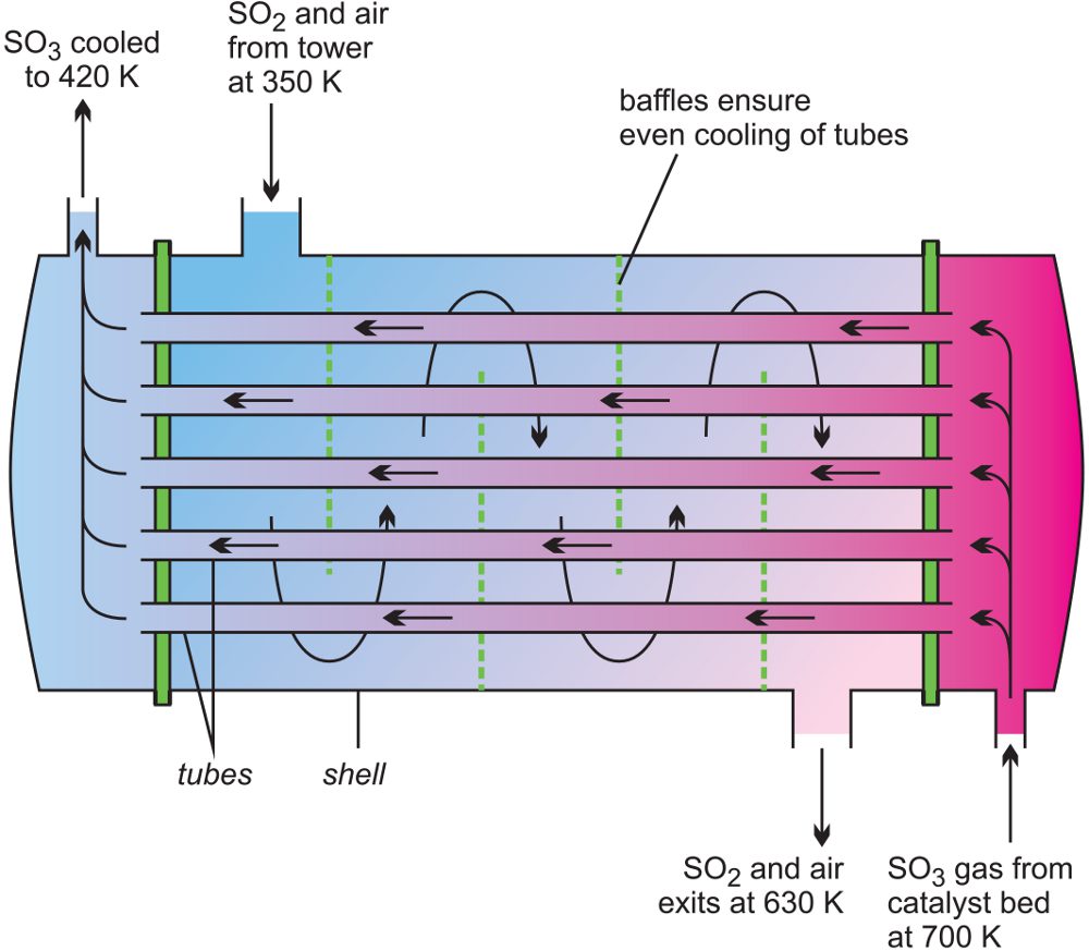
Figure 12 Illustrating a heat exchanger used in the manufacture of sulfur trioxide.
Thus the rate of heat transfer required will determine the size of the exchanger but when a chemical reaction also occurs in the exchanger (as in the case of tubular reactors ), it is important to take into account the residence time of the materials (whether they be gases or liquids) in the heat exchanger.

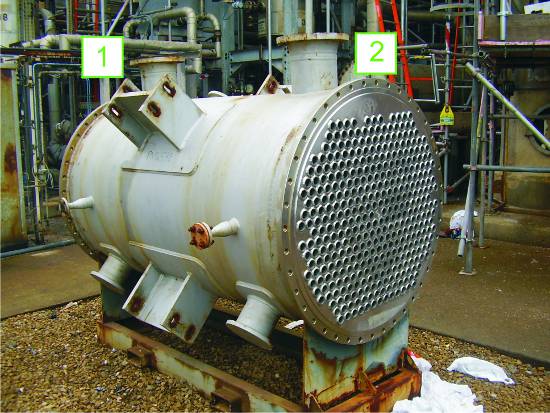
Figure 13 This exchanger is used for cooling product with water which enters the
shell side at 1 and leaves at 2. The product to be cooled flows through the
small tubes. The exchanger has been taken out of service to clean the tubes
to improve the efficiency of the cooling process.
Another example of a heat exchanger is the condenser at the top of a distillation column. Here heat from the vapour emerging from the top of the column is removed by, for example, cooling water. The vapour cools down and condenses and the temperature of the water increases.
Some developments
In the future many chemicals may be produced in reactors about the size of a large desktop computer, known as microreactors. The reduced size will lead to a reduction in capital costs and a reduction in the amount of chemicals in use at any one time, resulting in an inherently safer process.
The temperature can be kept constant more readily (as there is a much larger surface for a given volume). This allows for a very efficient heat transfer from the reaction to the surroundings even for very exothermic reactions such as the nitration of an aromatic hydrocarbon which can potentially be explosive.
There is considerable amount of research being carried out in developing microreactors. One example is the possibility of the direct conversion of benzene to phenol. A mixture of benzene and oxygen is fed through an alumina tube, packed with palladium at ca 350-400 K and hydrogen gas is passed over it.
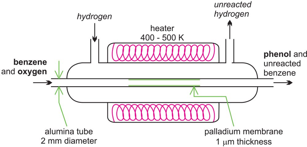
Figure 14 A microreactor being used to produce phenol from benzene.
Hydrogen permeates through the alumina tube, and is converted to atomic hydrogen by the palladium catalyst. The hydrogen atoms react with oxygen, releasing reactive oxygen species, such as hydroxyl radicals, which in turn react with the benzene to form phenol.
Another development is known as oscillatory flow mixing. Chemical engineers are designing reactors where the fluids to be reacted are oscillated inside a reactor with baffles at frequencies between 0.5 and 15 Hz with amplitudes in the range 1 to 100 mm. This allows for very effective mixing of the reactants and also for heat to be transferred to the surroundings. This gives similar conditions to those in plug flow which are otherwise difficult to achieve with small quantities of materials.
Date last amended: 18th March 2013